FINE BLANKING
1. EXPLANATION OF THE TERM:
Fine blanking is the term applied to an accurate method of cutting
having the possibility to produce components with straight edges, with better finish
conforming to ISO quality 7 (IT7) Because of combined action of the fine blanking
press and tool there is no crack formed at the cutting zone. Because of the perpendicular
cut resulting in straight cut surfaces, in many cases, it is possible to eliminate
.further finishing operations.
The plain surface will be straighter than that obtained by conventional
blanking operation. Fine blanking is not burr free blanking. The burr will be less
because of lesser clearance between the punch and the die. If the burrs are to be
completely eliminated then further operations like tumbling or belt sanding (limiting)
must be resorted to. ·
2.APPLICATIONS:
Initially fine blanking parts were used mainly for office machinery
industry. But now it is used in industries namely electrical industry, watch industry,
automobile industry, photography, audio, and video and aircraft industry.
3.WORKING PRINCIPLE:
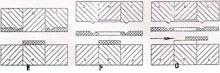
Fine blanking tool is a special tool incorporating the smaller
clearance (0.01mm or even lesser). The Vee ring around the counter is pressed on
to the sheet giving a relatively greater press force on the cutting line. The actual
working is in seven stages, which is given schematically in the figure.
a.Die block. b .Punch c.Press plate with V-ring d).Ejector E) Strip
OPERATIONS:
- Strip is fed
- Locating and pressing with V-ring
- Blanking and tensioning th_e ejector.
- Strip is lifted by the punch.
- Component ejected.
- Stripping
- Component removed from the tool.
The Vee-Ring
In order to better cutting of the cut surface, pressure is given
from all the sides taking care
For ex. see that during the blanking process the tensile limit
is not reached at the cutting zone. This is done by the
means of the V-ring. The usual shape and the dimensions are given
in fig & Table respectively.
|
s
|
g
|
h
|
|
|
1-4
|
>0.02
|
0.2S
|
0.66-0.75
|
|
|
20.02
|
0. 17S
|
0.65
|
STRIP WIDTH AND THE MARGINS:
Because of the presence of the V ring the margins and hence the
strip -width must be slightly larger than in conventional blanking. Figure (3) and
table (2) gives the typical layout and the margins. Some design 'fS take C/2 = 1.5s
and b = 2s.
's' = sheet thickness
THE PRESS FORCE:
The press force is a combination of the three forces as illustrated
in the figure (4). FB is the blanking force. FR is the force of the V-ring and Fe
is the counter force.
FB=L X shear strength
L x S x Tmax.
= cut length x sheet thickness. .
FR = 0.4 to 0.6 F.
F = L x f H
'f = specific counter force. 20 to 70N/mm2.
Note: A high counter force will overload the punch.
CLEARANCE/SIDE:
or punch diameter
D = 1.2s - clearance 0.5%.
D = 0.8 - l.2s - clearance 1%s.
"D = 0.6 - 0, 8s - clearance 1.2%s.


COMMENTS